1 / 2
| Length × Width (mm) | Dimensional Tolerances (mm) | Standard Thickness (mm) | Thickness Tolerances (mm) |
|---|---|---|---|
| 10 × 10 | ±0.1 | 0.5 / 1.0 / 2.0 | ±0.05 ~ ±0.1 |
| 20 × 20 | ±0.1 | 0.5 / 1.0 / 2.0 / 3.0 | ±0.05 ~ ±0.1 |
| 30 × 30 | ±0.1 | 1.0 / 2.0 / 3.0 | ±0.05 ~ ±0.1 |
| 40 × 40 | ±0.1 ~ ±0.2 | 1.0 / 2.0 / 3.0 / 4.0 | ±0.08 ~ ±0.1 |
| 50 × 50 | ±0.1 ~ ±0.2 | 1.0 / 2.0 / 3.0 / 5.0 | ±0.08 ~ ±0.1 |
| 60 × 60 | ±0.2 | 2.0 / 3.0 / 5.0 | ±0.1 |
| 80 × 80 | ±0.2 | 2.0 / 3.0 / 5.0 | ±0.1 |
| 100 × 100 | ±0.2 ~ ±0.3 | 2.0 / 3.0 / 5.0 | ±0.1 |
| 150 × 150 | ±0.3 | 3.0 / 5.0 | ±0.1 ~ ±0.2 |
| 200 × 200 | ±0.3 ~ ±0.5 | 3.0 / 5.0 | ±0.1 ~ ±0.2 |
All dimensions, thicknesses, and tolerance values displayed across the chart are measured in millimeters (mm) unless specified otherwise.
Larger surface areas (such as 150×150 mm and 200×200 mm) undergo broader thermal and mechanical variations during precision cutting, requiring a standard tolerance buffer between ±0.3 mm and ±0.5 mm.
Yes. Custom high-precision machining, diamond-wheel grinding, or laser cutting can achieve tighter dimensional and thickness tolerances upon engineering review and request.
Smaller dimensions (10×10 mm, 20×20 mm, and 30×30 mm) support ultra-thin profiles including 0.5 mm, 1.0 mm, 2.0 mm, and up to 3.0 mm thicknesses with strict ±0.05 ~ ±0.1 mm tolerance.
Thickness consistency is verified using multi-point digital micrometers or optical non-contact profilers across the edges and center of each unit to ensure compliance within specified limits.
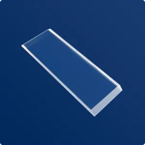
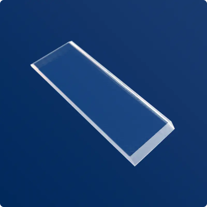
Yes, custom square, rectangular, and shaped geometries outside the standard reference table can be produced according to customized CAD drawings and thickness requirements.